Multiplikand – Manual
Quad Precision Mix-Multiple
Multiplikand is a compact routing utility module for Eurorack in 6HP. It takes Audio and CV, with optional DC filtering.
At its core, Multiplikand offers four active precision multiples, married to a unity-gain mixer.
Clever normalisation and a switch allow you to configure how the signals are summed.
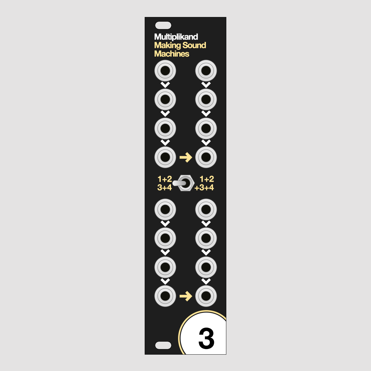
Here's a look at the front panel.
Why make another Multiple?#
We wanted both Multiple and Mix functionality in the same Module.#
When we use our Modular, we often record the dry signals into seperate tracks, plus an audio path with effects.
This allows us jam to our hearts content and still be flexible in editing.
Multiplikand is perfect for this: patch the incoming signals into one multiple each, split the dry tracks directly into an audio interface, then send Multiplikand's Mix into an effect.
We wanted it to work for Audio and CV.#
The Eurorack world offers plenty of passive multiples - which work fine for some patches, but are fraught with potential signal loss.
We designed Multiplikand as an active multiple, which means it can deliver a much more accurate copy of the signal.
That makes it suitable for duplicating signals that require a high amount of precision, such as pitch CV.
Multiplikand limits the Voltage it lets pass to its output - when you add very hot signals, they get clipped at +12V / -12V, suitable for Eurorack Audio and CV.
This is to keep you from overpowering the inputs of your other Eurorack modules with signal levels that are too high.
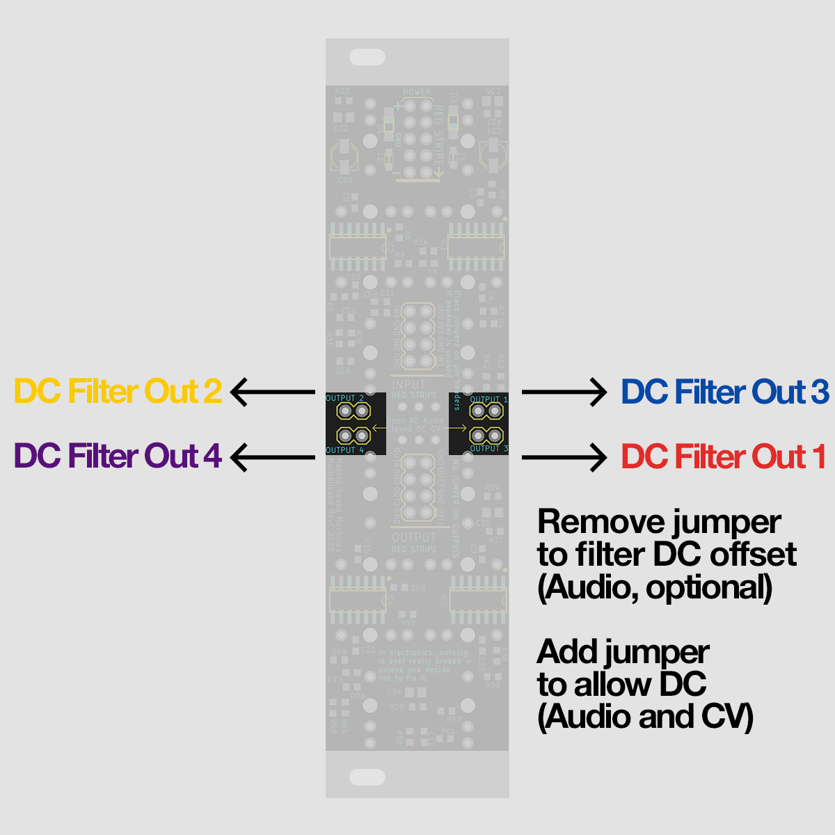
Jumpers on the back of the module let you opt-in to filter DC offset per channel, if you want to use Multiplikand exclusively for Audio.
Connect to power#
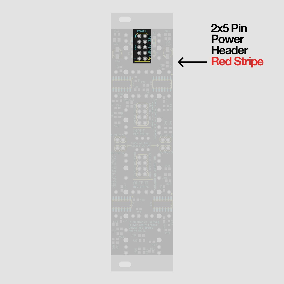
Multiplikand takes a standard 2x5 pin Eurorack power cable. We have included one with your kit.
The red stripe denotes -12V and is clearly marked on the PCB print on the back of your module.
Make sure you pay attention to the orientation of the cable both on your power bus and the module itself before you power up your system.
Multiples#
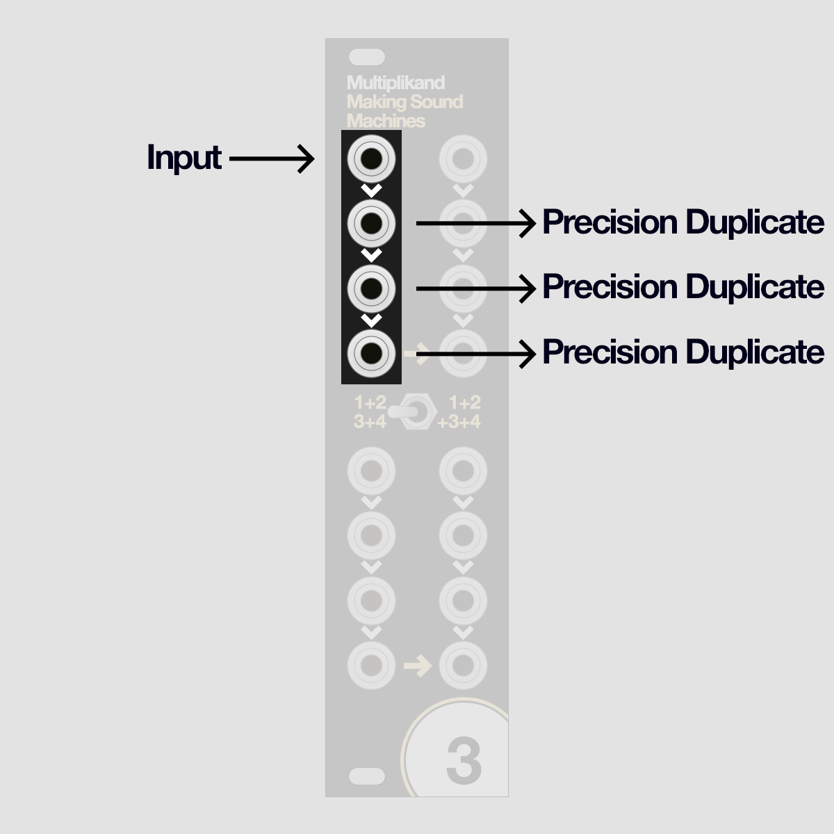
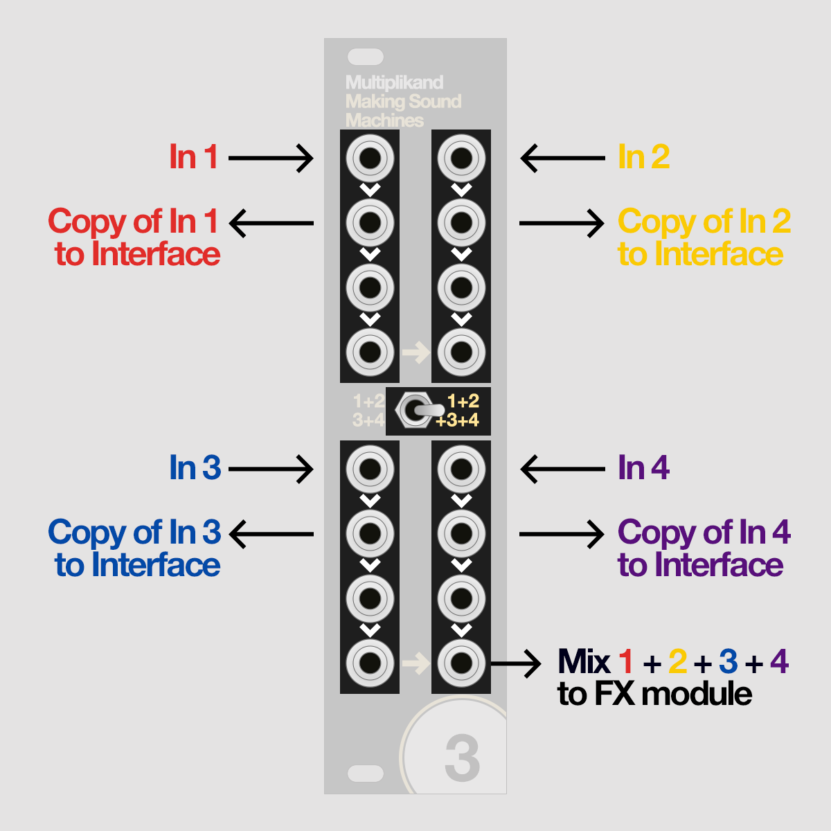
Multiplikand has four channels of active multiples, arranged in four identical-looking blocks at the top and bottom, left and right.
Patch an Audio or CV input signal into the jack at the top of the block, and you will get a copy of the same signal as an output from the three jacks beneath it.
A single channel of the active multiple looks like this.
Mix four channels: 1+2+3+4 Mode#
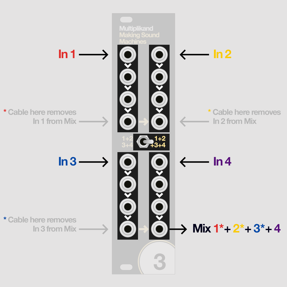
The bottom jack of each block holds a special function - it allows you to configure how the signals are summed.
Set the switch to the right position, labelled 1+2+3+4.
If you now patch four signals into the top of each block, so there is a signal present on In 1, In 2, In 3 and In 4, it will be output as an equal gain sum 1+2+3+4 on the bottom jack of the fourth channel, on the bottom right.
If you patch a cable to the bottom jack of channels 1, 2 or 3, that channel is removed from the sum on output 4.
Mix 2x2 channels: 1+2 / 3+4 Mode#
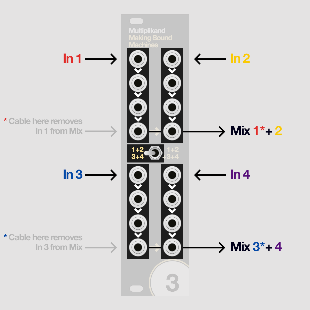
Set the switch to the left position, labelled 1+2 / 3+4, to group the mix into two groups of two channels instead of one group of four.
An input signal on In 1 and In 2 will now be output as a sum 1+2 on the bottom jack of the second channel, on the top right.
An input signal on In 3 and In 4 will be output as a sum 3+4 on the bottom jack of the fourth channel, on the bottom right.
Now, if you patch a cable to the bottom jack of channel 1, that channel is removed from the sum on output 2.
And if you patch a cable to the bottom jack of channel 3, that channel is removed from the sum on output 4.
Patch Examples
Stereo Send - Return#
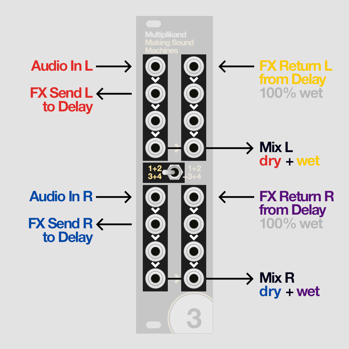
2x2 channel mode allows you to easily set up Stereo FX Send - Return patches. For this patch, set the switch left to 1+2 / 3+4 mode.
This type of routing is really helpful if you have a stereo signal and a stereo effect, and you want to mix both but still have extra patch points that carry the dry and wet signals - e.g. to record them as stems.
Patch the left channel Audio into In 1 and the right channel Audio into In 3. For each of these, patch a cable in to the jack below the input to get a duplicate of In 1 and In 3.
These will become your FX Send L and FX Send R, sending dry audio to your effect. Let's assume it's a Delay. Patch these into the L and R input of your Delay module and set it to 100% wet.
Patch the L and R output of your delay into In 2 and In 4. This will effectively make them your FX Return L and FX Return R.
On Out 2 and Out 4, you will now have an equal gain mix of wet+dry for left and right channels respectively.
Mono Send - Stereo Return#
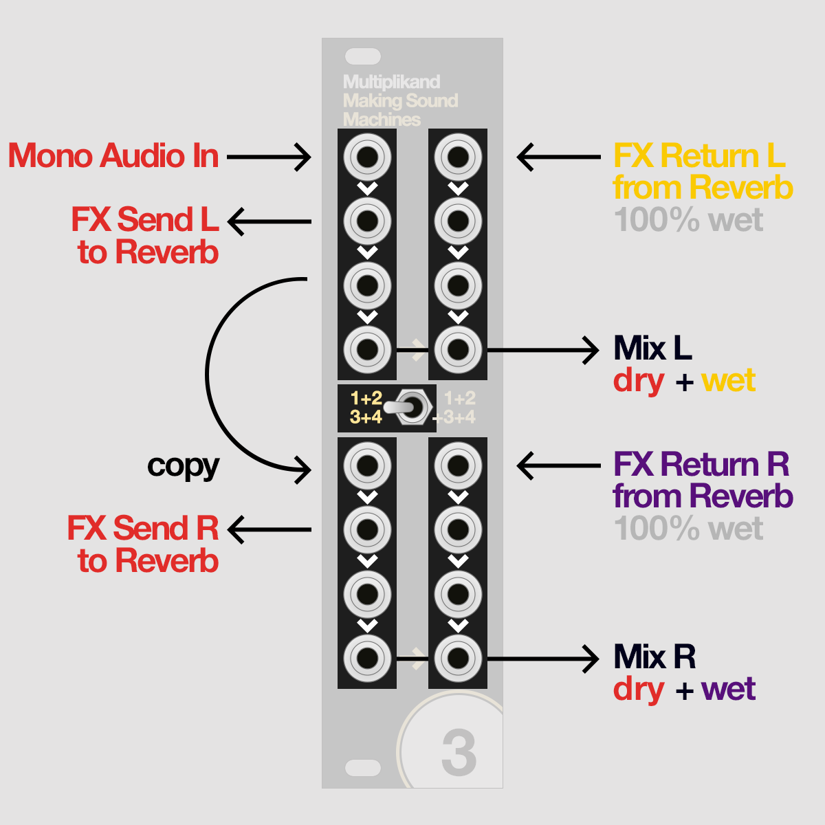
Setting up a Mono Send - Stereo Return patch is equally as simple. For this patch, the switch is set to 1+2 / 3+4 mode.
You can use this routing if you need to split a mono signal into a stereo effect, and want your mix to contain the dry mono signal on both channels as well as the stereo effect.
Patch the mono Audio into In 1. Patch a cable in to the jack below get a duplicate of In 1. This is your FX Send L.
Patch another cable in to the third jack on channel one, and patch a duplicate of In 1 to In 3. A cable below In 3 is your FX Send R.
Connect these with the L and R input of your effect, say a Reverb module, and set it to 100% wet.
Patch the L and R output of your Reverb into In 2 and In 4. This will effectively make them your FX Return L and FX Return R.
On Out 2 and Out 4, you will now have an equal gain mix of wet+dry for left and right channels respectively.
Stem 4x Drums and send Mix to FX#
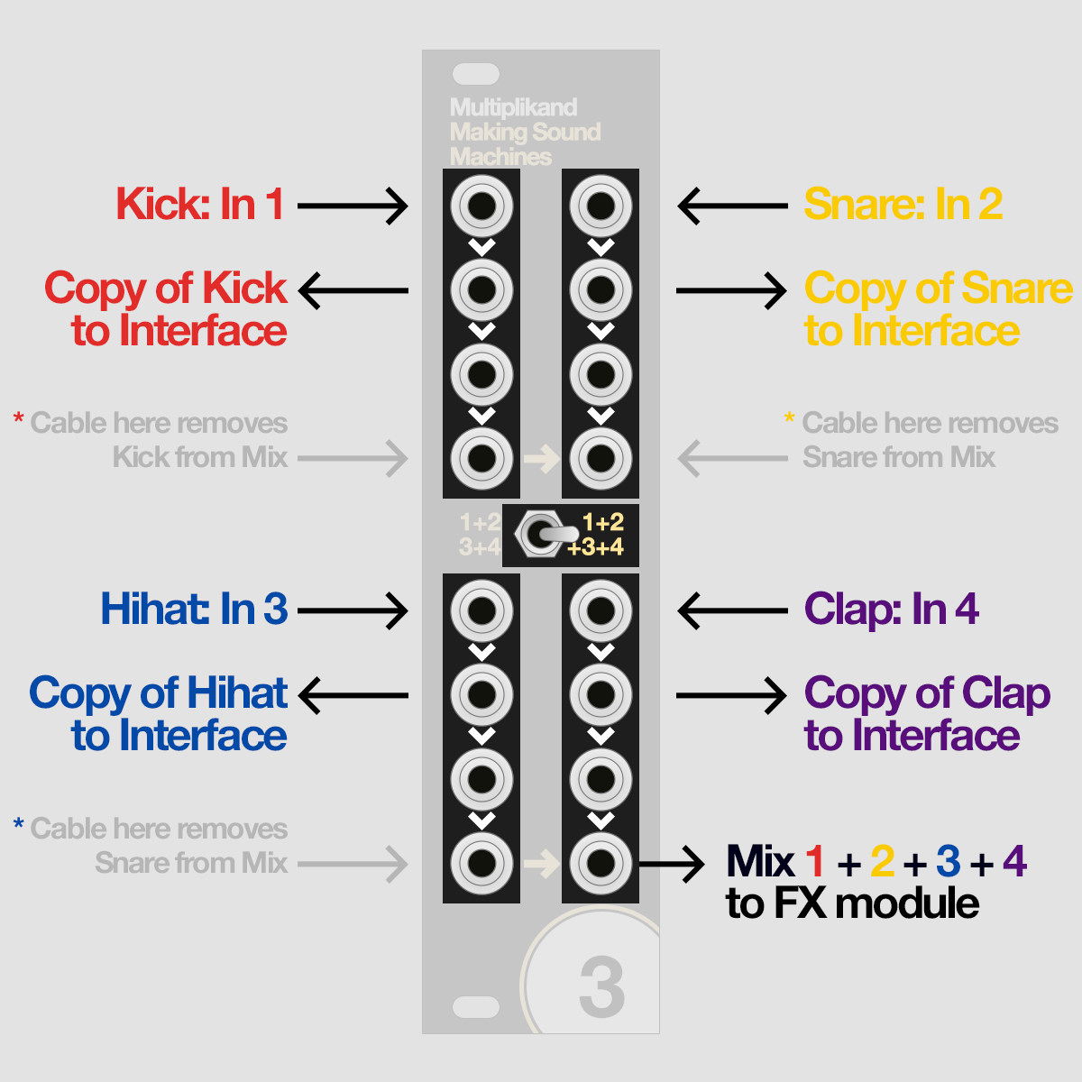
Here's a useful setup if you want to record the dry Stems of four Drum signals and send their Mix to an effect. For this patch, the switch is set to 1+2+3+4 mode.
Patch a Kick into In 1, a Snare into In 2, a Hihat into In 3 and a Clap into In 4. These could of course be any kind of drum sound.
Patch a cable in to the jack below each input get a duplicate of Kick, Snare, Hihat and Clap to record into your Audio Interface.
On the bottom jack of the fourth channel, on the bottom right, you will now have a mix of Kick + Snare + Hihat + Clap to send to the input of your FX module.
If you patch a cable to the bottom jack of channels 1, 2 or 3, that channel is removed from the sum on output 4.
Transpose a pitch CV sequence#
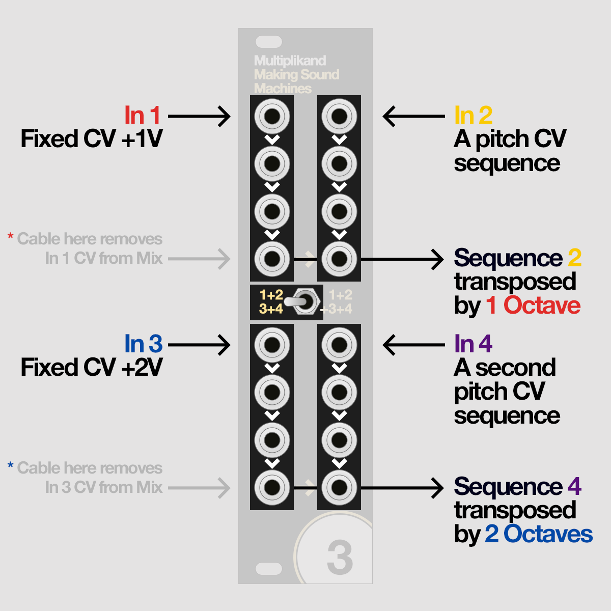
Here's a nice patch if you want to transpose two independent pitch sequences. The mode switch is set to 1+2 / 3+4 routing.
Patch a V/Oct CV sequence into In 2, and another V/Oct CV sequence into In 4.
These could be sequences you generate on a Beatstep Pro, Turing Machine, a Performer or any other CV capable sequencer.
Patch a +1V signal to In 1, and a +2V signal to In 3.
As one Volt equates to a pitch offset of on octave, you will get a version of Sequence 2 transposed by 1 Octave on the bottom jack of channel 2; and a version of Sequence 4 transposed by 2 Octaves on the bottom jack of channel 4.
If you want to take the idea one step further, try sequencing the transposition signals on In 1 and In 3 and get observe how sequences and transpositions interact.
Add LFOs to create complex Modulation#
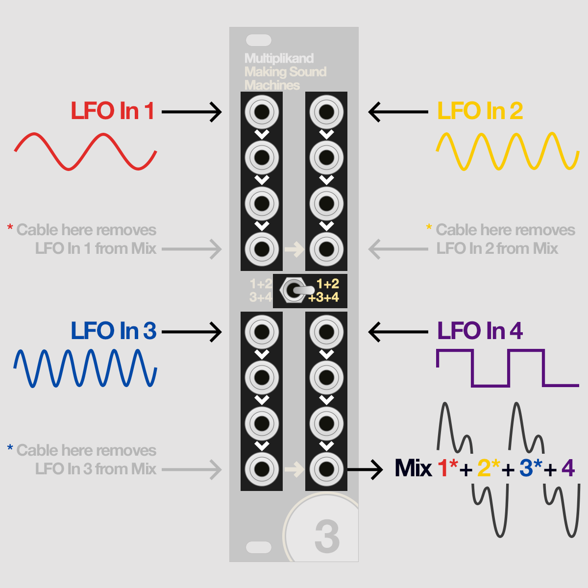
This patch adds four LFOs to create comples modulation. The mode switch is set to 1+2+3+4 routing.
Patch an LFO each into In 1, In 2, In 3 and In 4. Set them to different waveforms and frequencies.
On the bottom jack of the fourth channel, on the bottom right, you will now have a mix of LFO 1, LFO 2, LFO 3 and LFO 4 to send to the CV input of your module.
Try with the V/Oct input of an oscillatior or the cutoff of a lowpass filter to hear the effect of the complex wave shapes you can achieve this way.
If you patch a cable to the bottom jack of channels 1, 2 or 3, that channel is removed from the sum on output 4.
Patch a cable in to the jack below each input if you want to get a duplicate of LFO 1, LFO 2, LFO 3 or LFO 4 as a modulation source for another parameter or module.
Hack it! A look at the pinheaders
Note
Anything beyond this point requires at least a basic knowledge of electronics.
Inputs and Outputs#
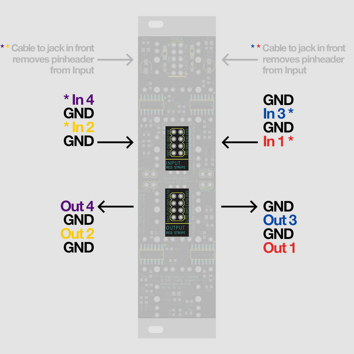
Multiplikand's input pinheaders are half-normalled with the input jacks in the front:
If you patch a cable into the front input jacks of channels 1, 2, 3 or 4, the signal from pinheaders 1, 2, 3 or 4 is removed from the input signal path.
The pinheaders come in pairs of signal and GND; If you have nothing connected to one or more of the input headers 1, 2, 3 or 4, it is imperative that you close the connection to GND with a jumper.
An open connection will make the module succeptible to noise and ground hum.
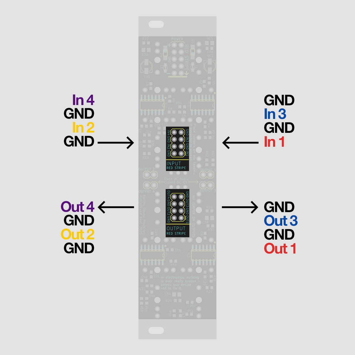
Multiplikands output pinheaders duplicate the signal from the front jacks:
A signal on the front output jacks of channels 1, 2, 3 or 4, will be equally present signal on the pinheaders 1, 2, 3 or 4.
Connect to Arduino, Teensy and Daisy#
When prototyping ideas, nothing is more fun than whipping up a quick sketch on a prototyping platform.
Writing a few lines of code, then uploading your sketch to an Arduino, Teensy or Daisy, allows you to play with your DSP idea in the physical world.
Multiplikand enables you to bridge the gap to Modular: pinheaders in the back allow you to patch jumper wires from your proto board to Multiplikand's inputs.
Warning
Keep in mind that the microprocessors on prototyping boards only work within certain voltage ranges, beyond which you damage the processor.
Multiplikand's ins and outs work in a voltage range of +/-12V, suitable for Eurorack Audio and CV.
Prototyping boards usually deliver and take 0 - 5V or 0 - 3.3V on their pins.
You can therefore safely connect the output of your proto board to the input of Multiplikand. If you find the output voltage of your proto board is too low, we suggest boosting it with our other DIY Boost module, Tausend dB.
However if you want to connect Multiplikand's output to your proto board, you need an additional overvoltage protection circuit before the inputs of your proto board,
to limit the incoming voltage to 0 - 5V or 0 - 3.3V.
Read the datasheet of your proto boards - ask for help if you are uncertain.